Traverse Editor
Traverse Editor
Ribbon: Survey → Traverse
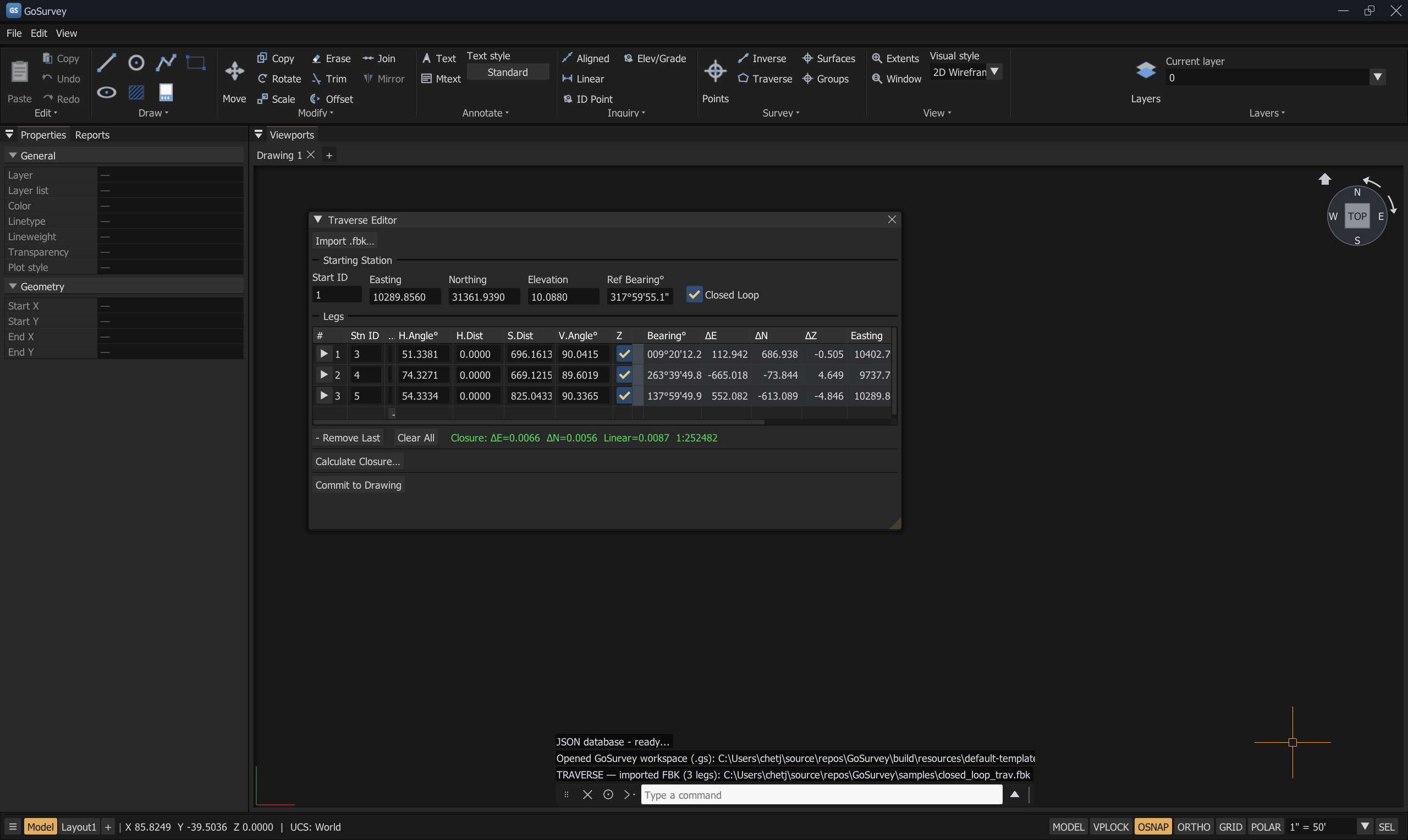
The Traverse Editor after importing samples/closed_loop_trav.fbk: starting station, three legs
with their computed bearings and coordinates, and the closure summary in green —
ΔE=0.0066 ΔN=0.0056 Linear=0.0087 1:252482.
The Traverse Editor works from raw field observations — horizontal angles, distances, vertical angles — rather than reduced coordinates. It computes traverse coordinates, runs a least-squares adjustment, reports closure with per-observation residuals, and commits the result to the drawing as survey points.
Starting station
Before any legs, set where the traverse begins.
| Field | Meaning |
|---|---|
| Start ID | Point number for the starting station |
| Easting · Northing · Elevation | Coordinates of the starting station |
| Ref Bearing° | Reference orientation at the start station (° CW from N). This is the azimuth of the backsight direction, or any reference mark. If you know the first leg's bearing directly, enter it here — the first leg's bearing then becomes this value plus the first row's H.Angle |
| Closed Loop | Tick when the traverse returns to the start station. Required for closure analysis |
Labels stack above their inputs so long field names stay readable.
Legs
Press + Add Leg to add a traverse leg; - Remove Last removes the last one; Clear All empties the traverse.
The collapsed summary row
| Column | Meaning |
|---|---|
| # | Leg number, with the expand arrow |
| Stn ID | Station number this leg arrives at |
| Desc | Station description |
| H.Angle° | Horizontal angle, averaged over all observation sets |
| H.Dist · S.Dist | Horizontal and slope distance |
| V.Angle° | Vertical angle |
| Z | Zenith flag for this leg |
| Bearing° | Computed bearing of the leg |
| ΔE · ΔN · ΔZ | Computed components |
| Easting · Northing · Elev | Computed coordinates of the station |
| Status | Per-leg state, including ✓ accepted after a least-squares result is applied |
The summary row is view-only on purpose — "Expand this leg to view and edit its individual observations." Edits are made in the observation sets, so a reduced value can never be typed over by accident.
Observation sets
Expand a leg to reach its observations:
Leg 2 → Station 103 — observations (2 sets)
| Field | Meaning |
|---|---|
| F1 Hz° / F1 VA° | Face 1 horizontal and vertical angle |
| F2 Hz° / F2 VA° | Face 2 horizontal and vertical angle |
| Zenith° checkbox | Checked = zenith angle (90° is level). Unchecked = elevation angle (0° is level) |
| Horizontal distance | Direct measurement |
| Slope (EDM) distance | Requires a vertical angle to reduce to horizontal |
+ Add Observation appends another set to the leg. Remove this observation set deletes one.
The leg's angle and distance re-average over all sets. Adding or removing a set re-derives the leg immediately — there is no recompute step for this.
Below the sets the editor shows Reduced (face-averaged) per-set statistics — a small table of
Quantity / N / Mean / Sum / Std Dev for Horizontal°, Distance, and Zenith° — and then the
reduction itself:
Horizontal distance: 696.1612 Slope distance: 696.1613 (zenith 90.04155°)
The Std Dev column is the fastest read in the dialog: a set that disagrees with its siblings shows up here before it ever reaches the closure.
Closure
Press Calculate Closure… to open Traverse Closure Analysis.
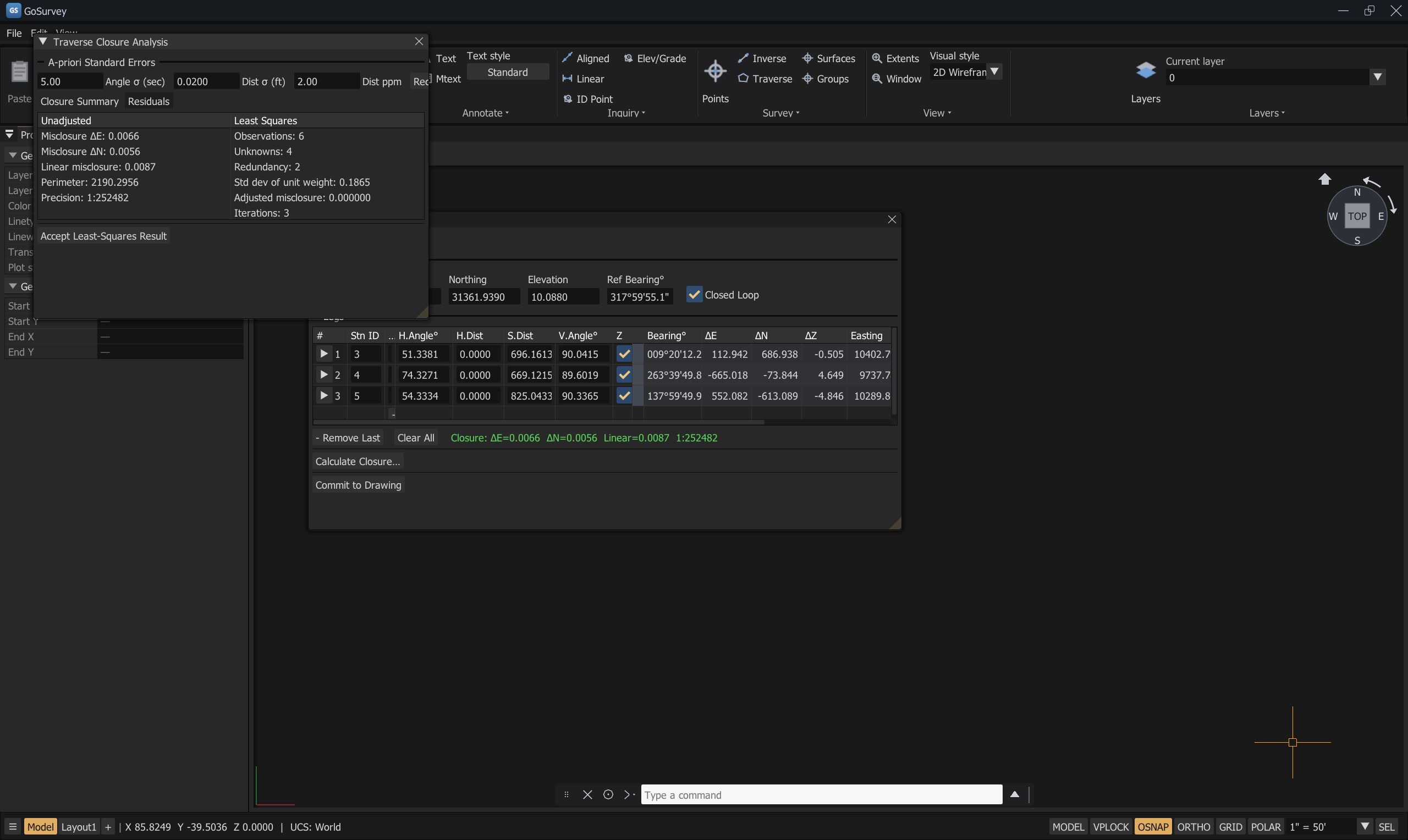
Closure Analysis on the sample field book: unadjusted misclosure and precision on the left, the least-squares result on the right.
Open the closure analysis: unadjusted misclosure beside a weighted least-squares adjustment, with per-observation residuals.
Closure requires a closed loop that returns to the start station. Without Closed Loop
ticked, the summary reads No closure (set Closed Loop and compute).
Unadjusted tab
| Value | Meaning |
|---|---|
| Misclosure ΔN / ΔE | The gap back to the starting station |
| Linear misclosure | Its magnitude |
| Perimeter | Total traverse length |
| Precision: 1:N | Perimeter divided by linear misclosure. A perfect closure reports Precision: perfect |
Least Squares tab
A weighted least-squares adjustment, solved in-tree — no external linear-algebra dependency.
A-priori standard errors — the weights you give the observations:
| Field | Meaning |
|---|---|
| Angle σ (sec) | Standard error of an angle observation, in seconds |
| Dist σ (ft) | Constant part of the distance standard error |
| Dist ppm | Proportional part, in parts per million |
Results:
| Value | Meaning |
|---|---|
| Observations | Number of observations used |
| Unknowns | Number of unknown parameters |
| Redundancy | Observations minus unknowns |
| Iterations | Solver iterations |
| Std dev of unit weight | How well the observations agree with the stated standard errors. Near 1.0 means the weights were realistic |
| Adjusted misclosure | Misclosure after adjustment |
| Residuals table | Per-observation Angle resid (sec) and Dist resid (ft) |
If the adjustment cannot run, the tab says Least squares unavailable: <reason> and
No residuals: <reason> rather than showing numbers you should not trust.
Recompute re-runs it after changing the standard errors.
Accept Least-Squares Result applies the adjusted coordinates to the traverse. The log confirms
TRAVERSE — accepted least-squares adjustment (adjusted misclosure …) and the leg is marked
✓ accepted.
Importing raw data — FBK
Import .fbk…
Import an Autodesk Field Book (.fbk) raw data file. Replaces the current traverse with the imported stations, backsight and observations.
This replaces the current traverse. Save or commit anything you want to keep first.
On success the log reports TRAVERSE — imported FBK (…); on failure,
TRAVERSE — FBK import failed: <reason>.
Sample field books are in the repository under samples/ — traverse_sample.fbk and
closed_loop_trav.fbk.
Committing to the drawing
Commit to Drawing writes the computed traverse stations into the drawing as survey points.
The log confirms TRAVERSE — committed points to drawing., and the operation is a single undo step
named Traverse commit.
From there the stations behave like any other survey points — snappable, labellable, exportable to CSV, usable in point groups. See Survey Points.
Reports
Traverse results are written to the Reports tab of the Properties panel, alongside ALIGN and exported-point reports.
A typical session
- Survey → Traverse.
- Fill in the Starting Station: ID, northing, easting, elevation, and the Ref Bearing° of the backsight.
- Tick Closed Loop if the traverse returns to the start.
- + Add Leg for each leg. Expand it and enter the Face 1 and Face 2 observations, setting the Zenith° checkbox to match how your instrument reports vertical angles.
- Read the computed bearings and coordinates in the summary rows.
- Calculate Closure… and read the Unadjusted precision.
- Move to Least Squares, set realistic Angle σ, Dist σ, and Dist ppm, and press Recompute.
- Check the Std dev of unit weight and the residuals. A residual far larger than the others points at a blunder — go back and check that observation.
- Accept Least-Squares Result.
- Commit to Drawing.
Common problems
| Problem | Cause | Solution |
|---|---|---|
| Closure shows nothing | The traverse is not marked as a closed loop | Tick Closed Loop and recompute |
| A summary field will not accept typing | Summary rows are view-only by design | Expand the leg and edit the observation set |
| Vertical angles reduce wrongly | The Zenith° checkbox does not match the instrument | Checked = zenith (90° level); unchecked = elevation angle (0° level) |
| A slope distance is ignored | No vertical angle to reduce it with | Enter the vertical angle, or use the horizontal distance field |
Least squares unavailable |
Not enough redundancy, or the geometry is degenerate | Add observations, or check for a duplicated station |
| Std dev of unit weight is far from 1 | The a-priori standard errors do not describe the real observations | Adjust Angle σ / Dist σ / Dist ppm to match your instrument |
| The FBK import wiped my traverse | Import replaces the current traverse by design | Commit or export before importing |
Related
Survey Points · Coordinate Alignment · Inquiry Commands · Import and Export